RAIL SERVICES
Many years’ investments allow us to offer the highest quality high speed contactless track rails based on modern machinery stock. The maximum length of the finished product is as much as 360m, which we will deliver to the project site.
The process offered is automated and computer-controlled so that the end result is significantly superior to the possibilities of exothermic track welding.
ELECTROFUSION WELDING OF RAILS
Poland's most modern rail welding plant allows the delivery of rails with a maximum length of 360m made from sections of 30m to 120m. The specialised machinery stock enables the supply of rails that meet the requirements of the 2019 PN-EN 14587-1 standard and the Technical Conditions Id-112 of 12.11.2013.
See how the rail welding process works:
Loading of rails onto the infeed table
Rails delivered on rail wagons are unloaded into our storage yard and then loaded onto the feeding table. Unloading and loading is carried out using special-purpose cranes equipped with crossheads and permanent magnets.
Transport of rails to the welding plant
The loaded rails are automatically taken from the feeding table by means of feeding trolleys and then transported by means of electro-rollers to the hall, where the basic welding process takes place.
Rail heating
In the line of electro-rollers transporting the rail to the welders, there is a system for automatic heating of the ends when the temperature of the rails to be welded falls below 50C.
Cleaning of contact surfaces
The heads, feet and rail faces are cleaned with an automatic brush to remove surface contamination. This activity is essential for a correct electrode-rail and railhead-to-railhead contact.
Electrofusion welding
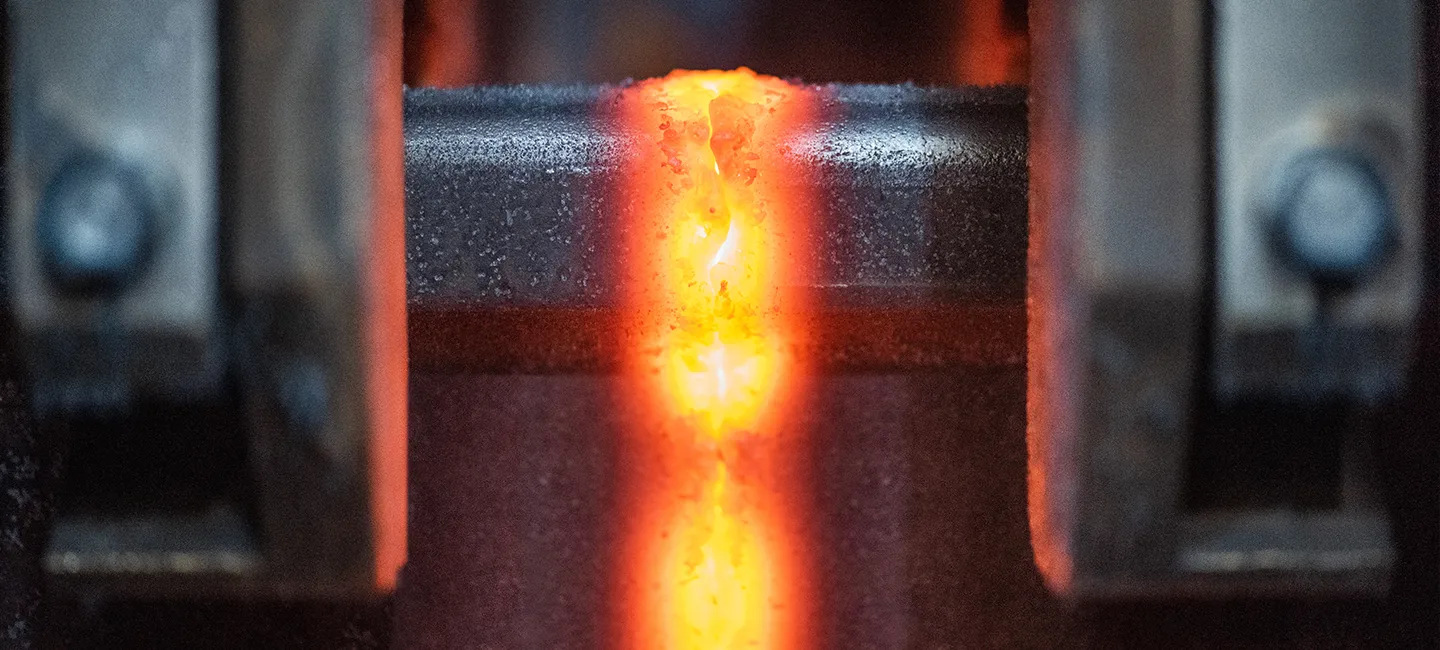
The cleaned rails are transported to the welding machine, where the automatic welding process is started. In the first step, the rail centering process takes place, in which the correct position of the rails is set in relation to each other so that any differences in rail height are transferred to the foot. The rail centering process is followed by a continuous welding process in corresponding steps:
- Pre-scaling - removes oxides, evens out face surfaces,
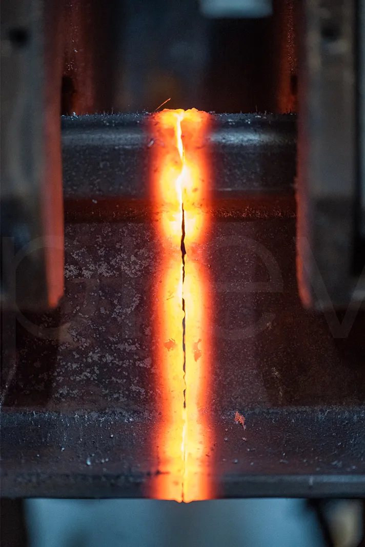
- Heating - heats the beginnings of the rails to the correct depth,
- Final sparking - cleans rail surfaces of any oxides that have formed,
- Bulging - very rapid pressing of heated rails for bonding, maintaining adequate compression force for a specified time,
- Trimming of the excess metal flash - the excess material created during swelling is trimmed to the appropriate height.
The welding process parameters are automatically recorded and continuously monitored by the welding machine operator. The entire welding process is presented in the form of a diagram and can be printed out and presented to the customer at any time.Marking
Each welded "long" rail is given an individual number, which is stamped on the neck of the rail using a pneumatic marker. In addition, each weld is marked with a corresponding number. The stamped numbers allow full traceability of both the weld and the entire rail.
Weld cooling
The welded and marked rails are transported by means of electrodes to an intermediate grate to cool the welds to the correct temperature.
Straightening and grinding
- Preliminary measurement and straightening
The welded rail with cooled welds is fed into a machining centre consisting of a press, grinder and laser measuring system.
In the first step, straightness is measured using three laser heads to determine whether the rail was bent about any axis during welding. The measurement result is presented in the form of a graph on the monitor screen. On the basis of the aforementioned graph, the operator corrects the straightness using the press cylinders, if necessary. The measuring and straightening operations are repeated until the straightness of the rail in the area of the weld reaches the appropriate straightness parameters.
- Grinding
The weld is then moved to the grinding station, where the machine grinds the rail in the weld area while maintaining the rail profile.
- Measurement, final straightening
After grinding the weld, the rail is returned to the press stand with the measuring system. The straightness is measured again and, if necessary, corrected with the press cylinders, so that the straightness in the area of the weld is within the specified range of dimensions.
The result of the straightness measurement is saved as a graph on the computer and is stored, and can be printed out at any time.Storage of welded rails
The grinded and straightened rails are guided out of the machining centre by means of electro-rollers and deposited on a storage grate by means of infeed trolleys. Then, by means of hoists equipped with crossheads and permanent magnets, they are deposited in the storage warehouse, where they are stacked. The same hoists can be used to load the rails onto specialised wagons for transport to the construction site. Unloading is carried out using a specialised unloading wagon operated by our own employees.
See process details
Rail cleaning
Both the head and face of the rail are cleaned of rust and dirt to ensure the best possible contact with the electrodes.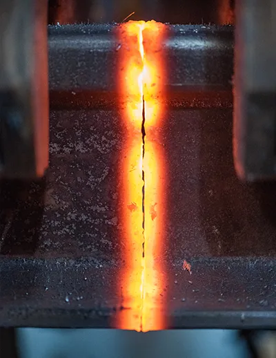
Sparking
Heats up contact surfaces and removes dirt residues.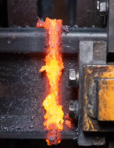
Bulging
The rails are pressed with great force which guarantees meeting the requirements ID112 and PN EN 14587-1 for rail welds.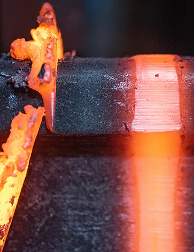
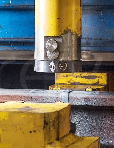
Trimming of the excess metal flash
Excess material is trimmed to the contour of the rail.
Measuring and straightening
The cooled rail is measured with three laser heads for straightness in 2 dimensions. The computer then calculates the force and pressure point to correct deviations from the standard.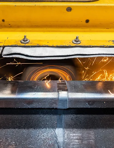
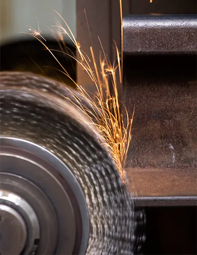
Grinding
The machine grinds the head of the rail on the side and top to maintain the required curvature.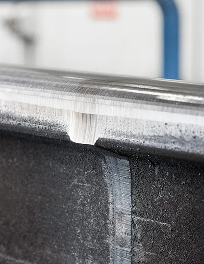
Sanding effect
Smooth surface rail for high-speed rail.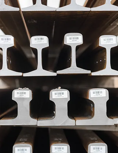
Storage
The rails are marked with a pneumatic marker and receive a sticker with identifying information.
Rail cutting
For rail profiles: 49E1, 60E1, 54E1, 54E4, 115RE we offer cutting from input material with a maximum length of 120 mb to the length required by the customer (maximum 32m) in the following cutting tolerances:
- ≤ 24 m - ± 3 mm
- > 24 m ≤ 32 m - ± 4 mm
Perpendicularity of rail ends 0.6mm in each direction.
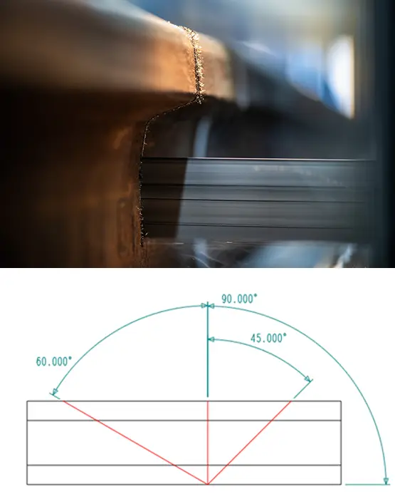
Angled rail cutting - see drawing on the left.
Rail boring
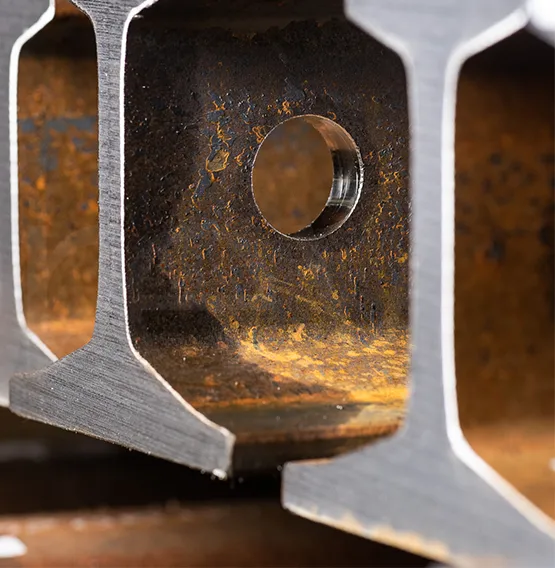
We also carry out the neck hole drilling of the aforesaid rails from Ø 8 mm to Ø 33 mm.
Hole position tolerance: ± 0.5 mm in each direction.
Switch blades 60E1A6, 60E1A1, 49E1A3 similarly to rails are cut from input material with a maximum length of 120 mb to the length required by the customer (maximum 32m) in the following cutting tolerances:
- ≤ 24 m - ± 6 mm
- > 24 m ≤ 32 m - ± 10 mm
Perpendicularity of rail ends: 0.6mm in each direction.
